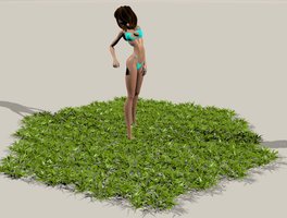
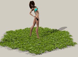
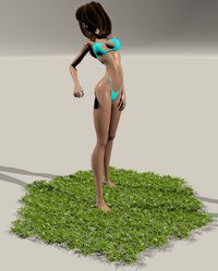
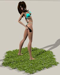
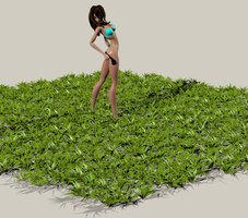
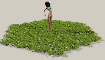
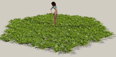
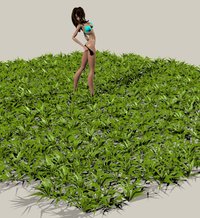
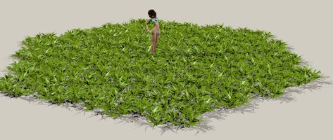
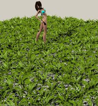
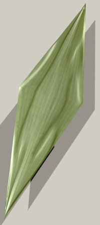
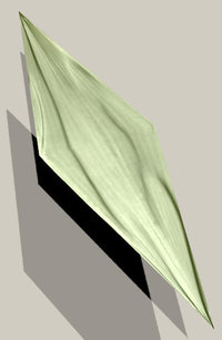
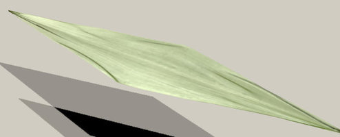
Don't forget that any feedback, thoughts, suggestions, ideas etc are very welcome.
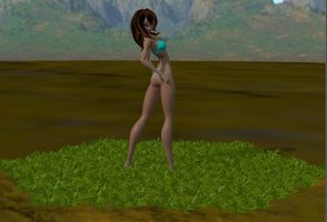
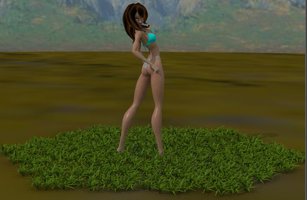
Off on a slightly different tack now - if I use one of the 'new' (888 vertices, 288 faces) alternate geometries (i.e. number 6 to 10) for each hex that makes the whole figure 32,856 vertices, 10,656 faces. I now want to add a second figure, scaled up so that the whole of the first figure fits into its central hex (about 616% I think?). I can't use the same geometries as the first figure because that would result in grass six times the size of the first figure. A continuation of my original approach from back around
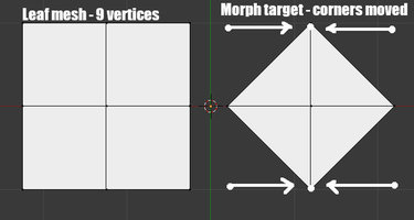
post #12 would be to randomize the hex rotations and geometries in Poser, export it as an OBJ, remove around 50-75% of the faces in Blender, and use that as the basic alternate geometry for the 616% figure. But at the back of my mind, and prompted by somebody's comment on this or another thread (my apologies to whoever suggested it as I can't find the post at the moment) I was wondering whether I could just create a displacement map based on the exported figure mesh and simply apply that to a two quad hex. Around twelve years ago I uploaded a (free of course)
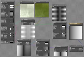
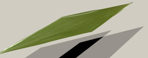
How To Model A Seamless Tiling Texture PDF to ShareCG, so I downloaded that again and gave it a try. Blender's UI's changed a bit, but it was still quite easy to follow - however, setting the bias for the displacement bake proved frustrating and I gave up. But then I thought why do the Z depth render in Poser itself? Well, for one thing Poser's Z-depth isn't actually Z depth, it's the distance from the camera to the point being rendered. Bagginsbill pointed this out somewhere once, but here's a simple Poser atmosphere Z-depth render using the top (orthographic) camera to prove it. The start/end distances for the shader below were obtained using a trial and error binary chop sort of guessing game
But then I thought about my own
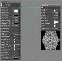
Z-depth shader fun and games and came up with this (the color ramp was just to help me find an appropriate value for y in the P node using the aforementioned trial and error method. For those who want something less empirical bagginsbill mentioned in a few places, none of which I can find at present, that the units of the P node are in
tenths of inches, and when you plug the output of a vector/color node into a
non vector/color node the input value is a third of the sum of the three components (e.g. below the output of P is (x,y,z), and the input of Math_Functions is (x+y+z)/3 )... or was it the square root of the squares of the sums? No, I think that was something else. The empirical trial and error method is good enough.
And here's the render, with a more detailed render of a small area
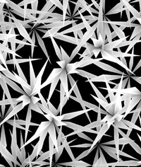
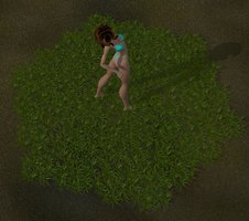
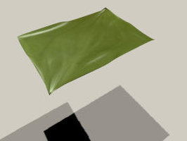
And here's that render applied as a displacement map to a green square. Displacement value empirically derived again. Note: on the image map it's important to set Filtering to None.
Far from perfect, but for mid distance grass it might work
